
Ionizing Detectors Based on Scintillation

Scintillation mechanism.
Ionizing radiation causes neutral atoms or molecules to acquire either a positive or negative electrical charge. The most commonly known types of ionizing radiation are alpha, beta, gamma, X, and neutron rays where alpha or beta rays, have a direct ionizing effect and neutral radiation, such as X, gamma, or neutron rays have an indirect ionizing effect. The detection and measurement of radiation are based upon the detection and measurement of its effects in a medium and among different widely practiced methods, one is by using scintillation detectors. Here we will be discussing detecting and measuring the scintillation when excited by ionizing radiation.
The use of scintillators includes new energy resource exploration, X-ray security, nuclear cameras, computed tomography, gas exploration, CT scanners and gamma cameras in medical diagnostics, and screens in older style CRT computer monitors and television sets.
Introduction to Scintillation and Scintillators
Scintillation is the produced flash of light (the property of luminescence) in a transparent material (material can be solid or liquid) when the particles like an electron, alpha particle, an ion, or a high-energy photon, excites the electrons within those materials and a scintillator is a material that exhibits scintillation.
Exactly saying, scintillators are materials that are able to convert high energy radiation such as X or gamma-rays to a near-visible or visible light.
The combination of a scintillator and a light detector is called a scintillation detector.
Scintillators are of two types in detecting ionizing radiation; one is the scintillation of organic scintillators and another is of inorganic scintillators. They have their own distinct requirements and features. Because of this difference in radiation length, inorganic scintillators are mainly used for X- and gamma-ray detection, while organic scintillators are mainly used for charged particle tracking.
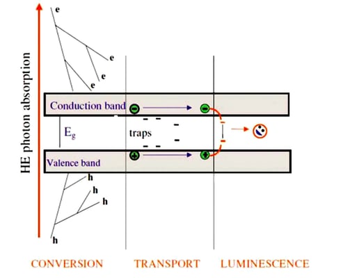
When ionizing radiation interacts with matter it will excite or ionize a large number of molecules. When these molecules return to the ground state, this will sometimes give rise to the emission of photons in the visible or near to the visible energy range and give rise to what we called scintillation (scientific name is radioluminescence).
Generally, the emission is for a very short time, but if the light emission continues for a long time after the excitation, i.e. much longer than 1 ms, this phenomenon is called phosphorescence rather than scintillation, and the corresponding- ing material is called a phosphor. Sometimes, the excited state is metastable, so the returning back down from the excited state to lower states is delayed for anywhere from a few nanoseconds to hours depending on the material. The process then corresponds to one of two phenomena: delayed fluorescence or phosphorescence.
Scintillation and the Cherenkov effect both are light emission effects, but the physical mechanism is completely different.
A scintillator can be gaseous, liquid or solid, organic or inorganic (glass, single crystal, ceramics) but should have the following properties to be useful as a detector for ionizing radiation:
-
the material must be chemically and mechanically stable
-
the efficiency of light production should be large
-
the amount of light emitted should be proportional to the energy deposited by the ionizing particle
-
the material should be transparent at the wavelength of the emitted scintillation light
-
the light pulses should be as short as possible and there should be little or no delayed light emission
-
the refractive index of the material should be close to 1.5 so that light can easily be extracted from the scintillator.
Detectors based on scintillators are essentially composed of a scintillator material and a photodetector that can be either a photomultiplier tube (PMT) or a photodiode. The role of the photodetector is to convert the outcoming light of the scintillator to an electrical signal.
Scintillators would not be very useful as detectors for subatomic particles without some device to convert the light signal into an electrical signal and that job is done by a photomultiplier tube.
Photomultiplier tubes are the most common photodetectors and photomultiplier tubes (PMT) contain a chain of dynodes. A dynode is basically a combination of electrodes and is arranged so that each succeeding generation of electrons is attracted to the next dynode and multiplies the electron generation emitting more than one electron when struck by a single electron that has been accelerated from a previous dynode.
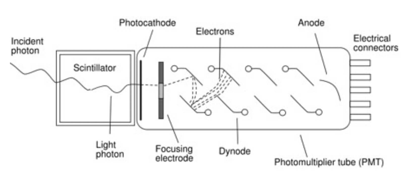
When the light photon strikes the photocathode, causing it to emit a photoelectron and those photoelectrons are focused on the first dynode. This produces electrons that are multiplied at the second dynode, and again at the third, all the way down the chain. The amplified signal is then collected at the anode and passed out to the measurement circuits. The obtained electrical signal is proportional to the number of photoelectrons.
Fabrication of Scintillators
The fabrication of scintillators can be done in two ways; Czochralski and Bridgman-Stockbarger method.
Czochralski method is usually used for materials with high melting points whereas the Bridgman-Stockbarger method is well suited for materials with low melting point and sensitive to air such as Strontium Iodide.
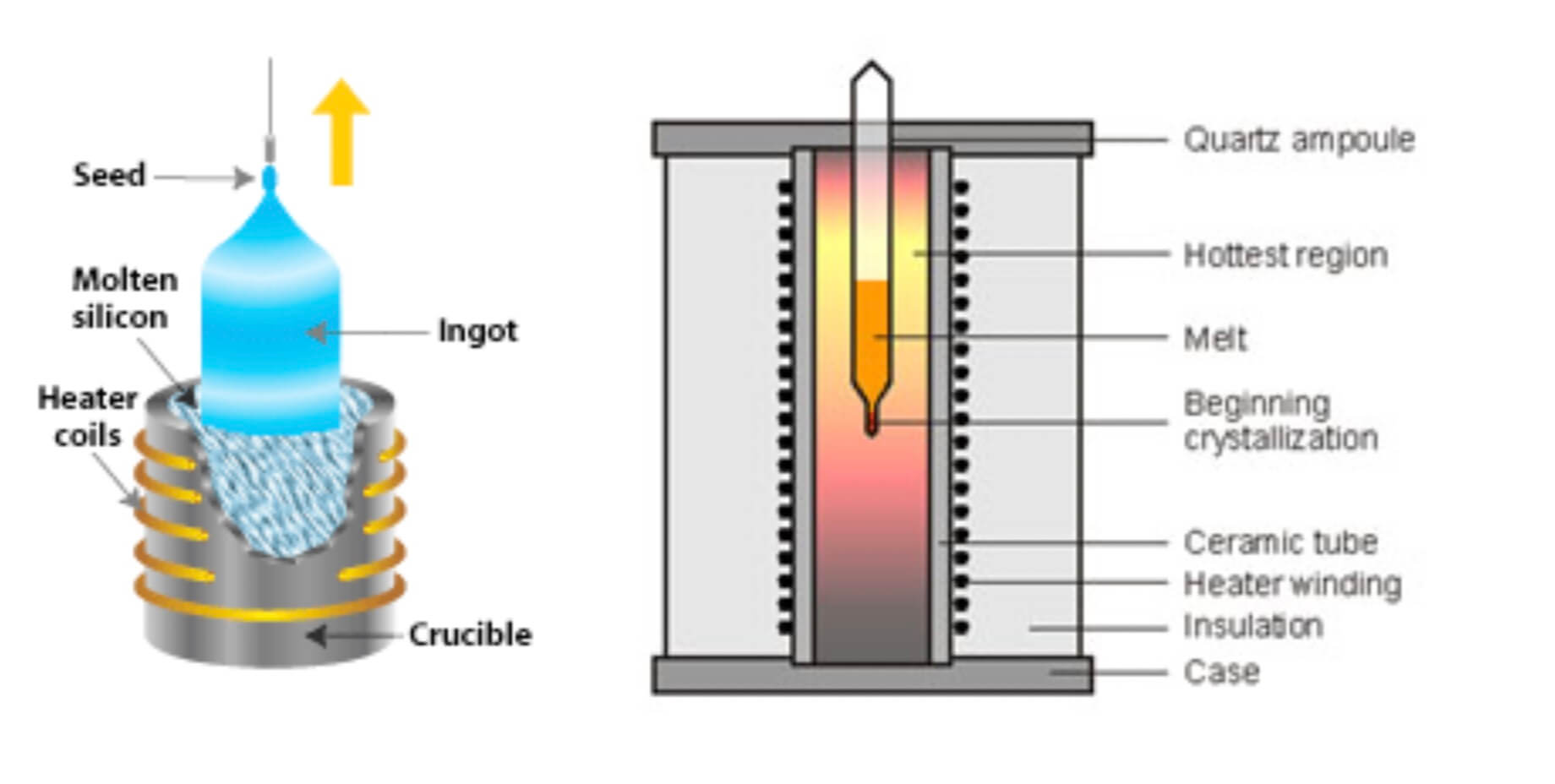
In the Czochralski method, we have to attach a seed crystal to the bottom of a vertical arm such that the seed is barely in contact with the material at the surface of the melt. Then the arm is raised slowly, and a crystal grows underneath at the interface between the crystal and the melt. Here the crystal is rotated slowly so that inhomogeneities in the liquid are not replicated in the crystal. For a controlled pulling effect, a computer-controlled apparatus is fitted and it can vary the pulling force to produce a desired diameter of the crystal. As the seed is extracted, the material solidifies, and eventually, a large circular boule is produced.
In the Bridgman-Stockbarger method polycrystalline material is heated in a sealed ampoule/vial. The heating maintains the molten state. As the ampoule is slowly lowered at a rate that matches the growth of the crystal into a cooler region, a crystal starts growing in the conical tip. The rate of moving the ampoule depends on the temperature and the material and this must match each other rate so that the interface between crystal and melt is always at the same temperature. When done successfully, the entire molten material in the ampoule grows into a single large crystal, and a layer of impurities grows at the interface between melt and solid as this surface moves up the melt, and the impurities become concentrated in the higher part of the crystal.