
To Find the Value of Acceleration Due to Gravity (g), Radius of Gyration (K), and Moment of Inertia (I) by using Compound Pendulum

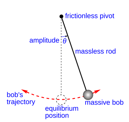
Diagram of simple gravity pendulum, an ideal model of a pendulum. It consists of a massive bob suspended by a weightless rod from a frictionless pivot, without air friction. When given an initial impulse, it oscillates at constant amplitude, forever. Image © Wikimedia Commons
Objective/ Aim:
-
To determine the acceleration due to gravity (g) by means of a compound pendulum.
-
To determine the radius of gyration about an axis through the centre of gravity for the compound pendulum.
Apparatus and Accessories:
-
A compound pendulum/A bar pendulum,
-
A knife-edge with a platform,
-
A sprit level,
-
A precision stopwatch,
-
A meter scale,
-
A telescope,
-
A spring balance and a graph paper.
Theory:
There exist different kinds of pendulums like simple, compound, double, and Kater’s pendulum. Typically a simple pendulum consists of a small body called a “bob” (usually a sphere) attached to the end of a string of certain the length whose mass is negligible in comparison with that of the bob. But this simple pendulum is a more ideal kind of pendulum and can not be realized in actual practice. Most of the hard to achieve defects are removed by introducing the concepts of compound pendulum.
Any swinging rigid body free to rotate about a fixed horizontal axis is called a compound pendulum or physical pendulum.
A compound pendulum consists of a rigid body that can oscillate freely about a horizontal axis passing through it.
The appropriate equivalent length L for calculating the period of any such pendulum is the distance from the pivot to the centre of oscillation.
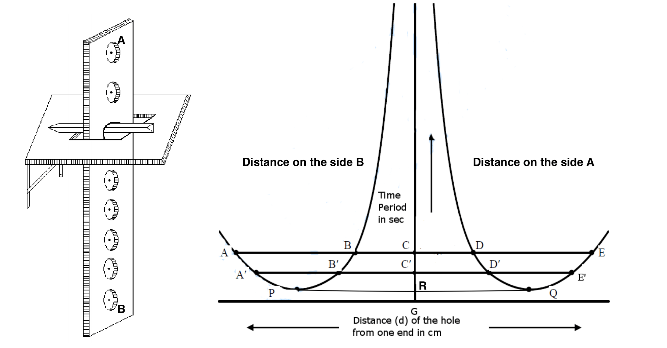
Figure below shows a compound pendulum where a body of mass M is pivoted about a horizontal frictionless axis through A and G' is the point after displaced from its equilibrium position by an angle θ. The distance between G’ and A is 𝑙.
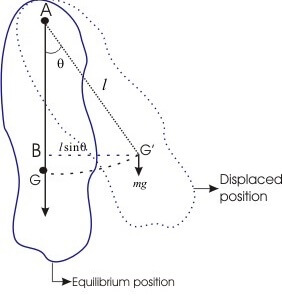
Now the restoring torque for an angular displacement θ is,
𝛕 = -MgG'B = -mglsinθ
For small angle displacement i.e. θ ~ 0, sinθ = θ
So, we may have,
Restoring torque, 𝛕 = -mg𝑙θ [Applied force and restoring torque are in opposite directions so the negative sign introduced]
Restoring torque rises to return an object (twisted, rotating, etc.) to its original orientation.
This restoring torque gives rise to an angular acceleration in the pendulum which mathematically means,
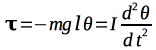
where 𝘐 is the moment of inertia of the body through the axis A.
where 𝘐 is the moment of inertia of the body through the axis A.
So we may get,

Where,

is constant.
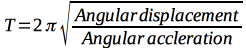
As the angular acceleration is proportional to angular displacement, the motion of the compound pendulum is simple harmonic and its time period 𝑇 is given by


Now
If IG is the moment of inertia of the body about an axis parallel with the axis of oscillation and passing through the centre of gravity G.
𝘐 = 𝘐G + m𝑙2
And 𝘐G = mK2 where K is the radius of gyration.
So,
𝘐 = mK2 + m𝑙2 = m(K2 + 𝑙2)
Finally we get
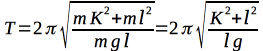
And length of an equivalent simple pendulum is
------- equation (A)
Where -------- equation (B)
is called the length of an equivalent simple pendulum or reduced length of the pendulum.
K2 is always a positive quantity and the length of an equivalent simple pendulum is always greater than 𝑙.
Then we get

And also equation (B) gives, 𝑙2 - 𝑙L + K2 = 0 -------- equation (C)
Since equation (A) have two roots, 𝑙1 and 𝑙2, and equation (C) is quadratic in 𝑙 we can get
L = 𝑙1 + 𝑙2 ------------- equation (D)
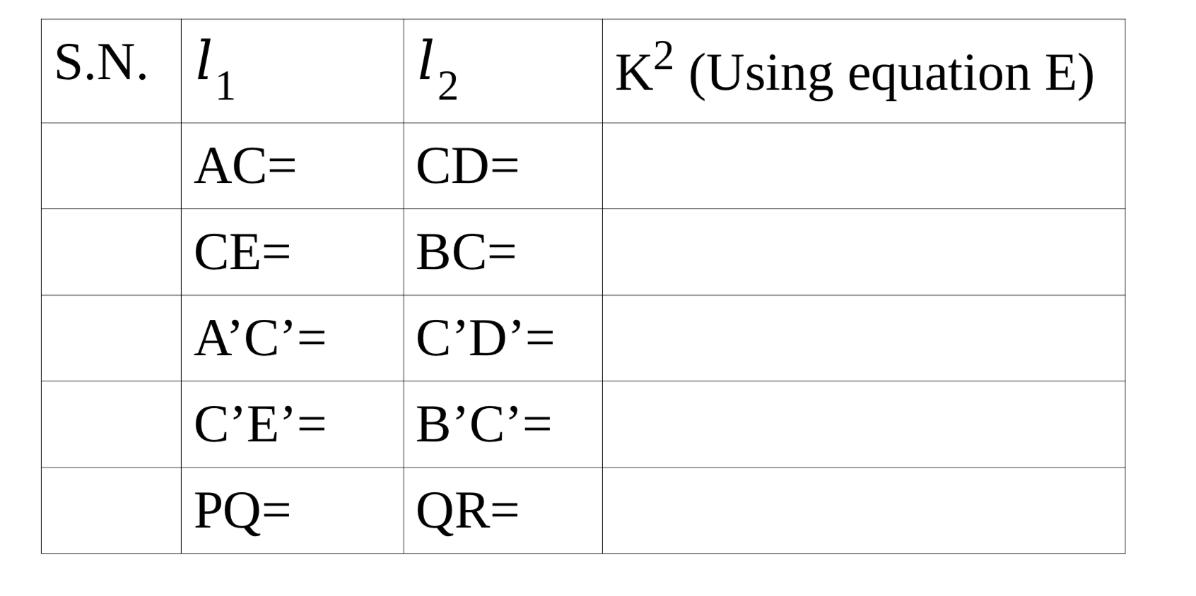
K2 = 𝑙1𝑙2 ----------------equation (E)
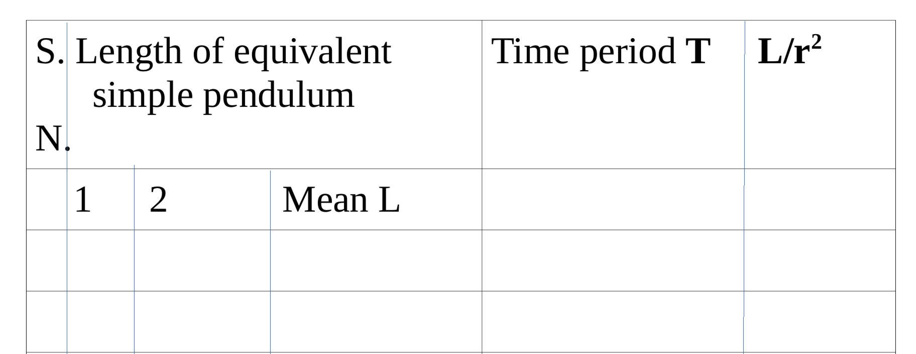
By determining L, 𝑙1, and 𝑙2 graphically for a particular value of time period (T), the acceleration due to gravity g at that place and the radius of gyration K of the compound pendulum can be determined.
Procedure and Description:
The bar pendulum (compound) consists of a metallic bar of about one meter long. A series of circular holes each of approximately 5 mm in diameter are made along the length of the bar. The bar is suspended from a horizontal knife-edge passing through any of the holes. The knife-edge, in turn, is fixed in a platform provided with the screws. By adjusting the rear screw the platform can be made horizontal.
-
Paste a small piece of paper or mark by any other sticking marking methods on either end of the compound pendulum. With these markers, draw a line parallel to the edge of the pendulum as a reference point. Mark them as points A and B as shown in the figure. Place the knife-edges in the first hole on either side parallel to each other and make them tight, so that the sharp edge is pointing towards the centre of gravity.
-
Place a spirit level on the glass plates fixed on the bracket in the wall meant for suspending the pendulum and see that the upper surfaces of the glass plates are at the same level.
-
Suspend the pendulum from the knife-edge on the side A so that the knife-edge is perpendicular to the edge of the slot and the pendulum is hanging parallel to the wall.
-
Adjust the eyepiece of the telescope so that the cross wires are clearly visible through it. Focus the telescope at the reference line of the compound pendulum. Turn the eyepiece so that the cross wires are in the position of the marking point.
-
Set the pendulum into vibration with a small amplitude of 5 degrees and allow it to make a few vibrations so that these become regular.
-
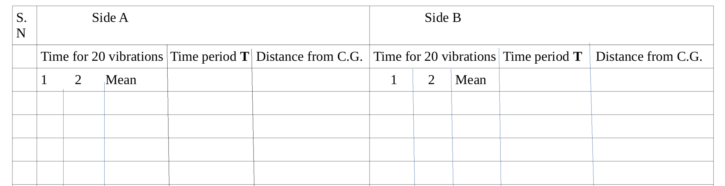
Look through the telescope and when the image of the reference mark passes across the point of intersection of the cross wires, start the stopwatch and count zero. Count one when the pendulum is passing through the same position in the same direction and so on. Note the time taken for 20 vibrations. Repeat again and time take the mean.
-
Measure the distance between the C.G. and the inner edge of the knife-edge.
-
Now suspend it in the knife-edge on the side B and repeat the same observations as above.
-
Repeat the observations with the knife-edges in the 2nd, 3rd, 4th, 5th, etc. holes on either side of the centre of gravity.
-
Tabulate the observation accordingly.
Now plot the graph;
To plot the graph,
-
Take the Y-axis in the middle of the graph paper. Represent the distance from C.G. along the X-axis and the time period along the Y-axis.
-
Plot the distance on the side A to the right and distance on the side B to the left of the origin. (Shown in the figure above)
-
Draw a smooth curve on either side of the Y-axis passing through the plotted points taking care that two curves are exactly symmetrical as shown in the figure above.
To find the value of acceleration due to gravity “g”;
-
Draw two lines parallel to X-axis that cuts the curves at points, let ABCDE, and A’B’C’D’E’ respectively on both sides of the Y-axis. Also, draw a line that touches points P and Q. [Shown in the above figure]
-
Select points like B and E, A and D, etc. (but not equidistance from it) on the graph on both sides of C.G. that have the same time period. Measure the distance AD and BE.
Similarly, measure the distances between A’D’ and B’E’ and so on.
Now use the value in the equation
Actual value of g is 9.8 m/s2
To find the radius of gyration (K);
Measure the distances AC, CD; BC, CE and A’C’, C’D’, B’C’, C’E’, as well as PR and QR. [In figure R is the point on Y-axis that joins P and Q].
Moment of inertia (I);
Find the mass of the pendulum.
Then,
You have the value of Mass of the pendulum (M) and radius of gyration (K)
And now the moment of inertia = MK2